8-bit CPU: Going virtual
Recap
I "went live" with the CPU and swapped out my Test module for EEPROM-based Control Logic. Now the CPU works stand-alone, but I still have the Arduino sketch and lots of Python code to command it. My long-term plan is to re-connect it and use for system diagnostics and program debugging, but for now I'll set it aside and go with a software implementation.
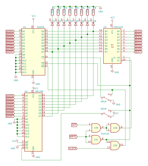
What exactly that Test module was and how did it work? It was an Arduino + few '595 shift registers and '138 demultiplexers. These were connected to control signals of the CPU modules. For example, if I wanted to output the contents of the A register onto the bus, I'd load the corresponding combination of bits (a Control Word) into the shift registers. The Arduino was also directly connected to the bus, making it possible to read what's there or inject values. Additionally, it acted as a clock module and issued pulses when necessary.
Overall, it gives the Test module full control of the CPU. By manipulating control signals, bus values and clock pulses, it could load values into RAM, emulate instruction execution, inspect contents of the registers - whatever is necessary.
The Test module was controlled via serial connection from Python scripts running on computer. The Arduino part was actually quite "dumb" - it just acted on commands and delivered results back. Commands like: load this Control Word, put a value on the Bus, issue a clock pulse, etc. Whole "smarts" were in the Python scripts. And, since all the instruction opcodes and steps were also configured in Python, it could even run code in "Assisted mode".
I've even developed a comprehensive test suite using PyTest framework, making it possible to exercise all the parts of the computer to see if all the wires are still connected.
Re-implementation in Verilog
Verilog hardware-description language sounds like a perfect fit to describe the CPU. If only I could make it "alive". A way would be to put it on a FPGA, but an easier option is to run it in Icarus Verilog engine. One can extend it using something called VPI modules. They're written in C, so I imagine they should be able to do whatever C can, solving the issue of communicating with the outside world.
To be able to mirror actual hardware, I started by writing a bunch of Verilog modules, implementing 74-series logic chips. I took extra care to make them behave exactly as described in datasheets. Then combined them into CPU modules (Registers, ALU, Program Counter) by "wiring" them as if they were real ones (no expressions or other language trickery, just wire components).
This way I'll be able to experiment, while keeping it possible to build same thing using real chips.
Then comes the Debug module. It uses a VPI extension to listen for UDP packets to get commands and send data back. Initially I made it to set up a virtual serial port, but found out later that UDP allows much more flexibility, and updating Python part for it was quite easy. As the Arduino sketch was quite straightforward, I was able to replicate it in Verilog surprisingly easy (obviously I had to use more language constructs than just wires).
It took a while to get everything right, but it resulted in an emulator that passed all my test cases as if it was real hardware. And was able to run programs and send back results fom emulated Output register.
I also implemented the Clock and ROM-based Control Logic. The Debug module keeps them disabled normally, but can yield control to them, making the thing run autonomously. Then it runs until some specific event (like rising edge of a HLT signal) drops it back into Debug.
GitHub Actions
Once I got a test suite that runs against virtual implementation, I decided to set up GitHub Actions, so that it is ran every time I update project on GitHub.


Comments
Post a Comment