8-bit CPU: ALU and Flags
Now that I have a pair of devices that can store a byte, I can proceed to do something more interesting. Build a device that add them together, for example. In other words - let's build an ALU.
The design follows same basic idea as Ben's - two 4-bit adders, XOR gates and an output buffer. I'm using HC logic here, so I used 74HC283, 74HC86 and 74HC245 chips.
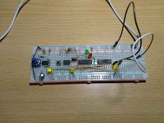
Since I've built only one Register and did not want to build another, I connected my Program Counter board as register B. If I keep the counting function disabled, it serves the purpose just fine.
It took a lot of wires, but I'm just getting started, let's build Flags register as well.
There were no surprises with Zero flag - 4 NOR and 3 AND gates does the job - just following the Ben's design. Another latch (74HC173) chip to store it, done.
The fun starts with the Carry flag: I wanted to support a carry-in signal for the ALU. It is very useful if one wants to perform the addition or subtraction for wider (16-bit or more) integer values. You add the lowest byte, store the carry, and then supply it to the addition of next bytes and so on. Same idea applies to subtraction, just the carry signal is called borrow instead.
In Ben's design the Carry line is hardwired to Subtract signal, I had to connect it differently. A bit of explanation:
- add with carry means "add one more", so 2 + 3 + C = 6;
- subtract with borrow means "subtract one more", so 3 - 2 - B = 0. The subtraction is internally performed with bit-wise negation, addition and adding one more. In this case, if we skip the "add one more" part, it acts same as "subtract one more". The expression becomes 3 + 254 + 0 = 0
Looks like the Carry/Borrow signal must be supplied as-is for addition, and inverted when subtracting. Sounds like a job for XOR gate.
What about carry/borrow-out? Ben connected the output from adder directly to the latch, but I'm not so sure about the case with subtraction. There are different scenarios:
- 3 + 2 = 5 (no carry)
- 3 + 254 = 1 (8-bit wrap-around, carry set)
- 3 - 2 = 1, there's should not be borrow, but internally it is executed as 3 + 254 (carry set)
- 3 - 254 = 5, should borrow, but internally that becomes 3 + 2 (no carry)
Again, looks like the carry/borrow-out signal should be inverted when subtracting. Job for another XOR gate.
I consulted AVR Instruction Set Manual for inspiration. In Conditional Branch Summary there's a nice table how various branching instructions can be implemented. But it appears that I need two more flags for it. Incidentally, there are two unused modules in the 173 chip.
Negative flag is simple: just store the most significant (7-th) bit of the ALU result.
There's one more: overflow (oVerflow for V). I found some theory on what it is and how to calculate it, but for it boils down to rule: "if sign of two added inputs were the same, but sign of the result differs, there was an overflow". Internally, sign is represented by most significant (7-th) bit. Rules for subtraction are bit different, but it does not matter, if we pretend that we perform only additions by comparing inputs and output as they are seen by adder chip.
One way to write it is (A == B) and (A != R), but since XOR gate can be used as != operator, it becomes not(A xor B) and (A xor S). There are 2 spare XOR gates in chip that was added for carry-in and carry-out conversions.
For NOT and AND we could add 2 extra chips, but let's add just one, containing 4 NAND gates. We can use one as NOT, another for ANDing, and then invert the result again.
I actually built the circuit this way at first.
However, we can reason about it a bit differently: if (A != R) and (B != R), then A should be equal to B, same condition we wanted to check. Using logic gates this boils down to (A xor R) and (A xor B). XOR gates are already there, we just need a single additional AND gate.
After poking around with some preliminary tests, I decided to hook it up to Arduino and do more diligent testing. To test everything we need to connect 7 control signals + clock + 8 bus lines + 4 flags lines. It might be possible to leave something out and test it partially, but I already faced lack of outputs when building EEPROM burner. Same idea fits here - just added a shift register for those control lines.
To be completely honest, I'm not convinced that the device deserves the name of Arithmetic Logic Unit, as it does not produce results of any logic operation, so I sometimes refer it to as just Arithmetic Unit.
I have, however, some plans to build similar modules for logic operations. A full functional computer might need support for AND, OR, XOR, NOT, SHR and SHL.


Comments
Post a Comment