8-bit CPU: EEPROM burner
In previous post I got to the point where I need to program an EEPROM, but have no device to do that. This time I'll try to build it.
Ben had similar side-build as part of his Output register, so this should be a replica of that, right? Well it could have been, but I did not follow his footsteps exactly.
First, I do not have Arduino Micro, just an Uno with a half-size breadboard attached to it. So I was planning to use that. I could not source 74HC595 shift registers, so I got 74HC594 instead. As it turned out later, they are so similar, that there actually are no differences for this use-case, but I did not compare them carefully at the beginning. Also, I was not following the video exactly, just got the main idea about shift registers and continued on my own.
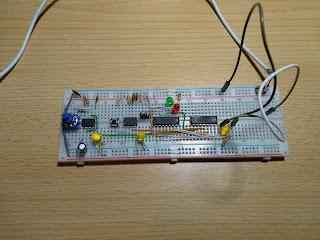
Placed the chips on the small breadboard, but there was a problem - the breadboard was a little too short. I placed chips end-to-end without any gaps in between, and there was just enough holes to fit all the pins.
Unfortunately, the case of AT28C64 extends a bit over the pins and it overlapped a bit with the chip next to it. The result was that I could not insert the EEPROM completely into the breadboard. But visually it looked like it still gets a connection.
Later it turned out to be a bad idea. I did not verify if it really connects (using a multimeter), and actually it didn't.
I went on to connect the outputs of shift registers to the EEPROM's address lines. With chips packed so tightly, there was no space to route the wires around to the other side neatly. Some of them needed to go around the whole assembly.
I'm not sure what happened when designers of those chips decided where address pins should be. Why A0 to A7 are located so conveniently, but other address lines just seems to be allocated randomly? But it appears to be standard, as my SRAM chips have the same layout.
Somehow I picked up the idea stated in the 74HC594 datasheet that one can tie SH_CP and ST_CP lines together. It basically means that output lines switches all the time while data is shifted in, staying behind by one clock pulse. To get the desired value on the output it will require an extra clock pulse at the end.
Adding an extra clock pulse is easy - just shift the address left one place in software, before sending it out. That will add an extra unused zero at the end, I'm not going to need all 16 bits anyway. Or so I thought.
In contrast, Ben pulsed the ST_CP line just in the end. It requires an extra wire, but is more straightforward approach. Mine actually caused me a lot of confusion later.
Now to the Arduino side of things. Ben used shiftOut() function to output the data. This works, but is a software implementation. From my previous experience with AVR microcontrollers, I know that ATmega328p contains a dedicated hardware, that can be used: SPI. There is a module in Arduino library for it and usage is not much harder than that of shiftOut(). It should work 15 times faster.
SPI can be used for bi-directional communications between microcontrollers, sensors, etc., but can as easily be used with shift register. There are 4 dedicated pins for that SS, MOSI, MISO, and SCK. They are accessible as Arduino pins 10 to 13. MOSI should be connected to data input pin of the shift register, and SCK - to SH_CP. The remaining 2 will remain unused.
For completeness: MISO can be used to read data in. SS is a control signal, that's used to signal that another device wants to talk to Arduino. When Arduino is controlling the transmission, it can be used as a normal output. But is useless as an input, because SPI hardware interprets low as another device taking over the control.
I learned about the SS and input mode the hard way - tried to use it for one of data lines coming from EEPROM. The whole thing just "locked up" when I tried to read back the data.
The software side also got some improvements. Ben's version started to write to the EEPROM immediately on startup. I added a "command interpreter", so that Arduino just sits and waits for instructions when powered up. Only when it receives a command from computer, it starts to write. What data exactly to generate and write: 7-segment, microcode or something completely different - it comes with the command.
Then I added feature that it reads the contents of address first. And only writes if the value needs to be changed. Then re-reads it afterwards, to see if it succeeded. I did not put much trust on it, did I?
But no matter what I did, I could not get anything written into the EEPROM. I started to suspect that it is not getting the connection properly. At some point I gave up and decided to move everything to full-size breadboard, obviously adding some spacing between the chips. Now some of the wires were not as neatly bent as before, I had to cut a few new ones, but everything was connected securely and started to show signs of life.
It worked somewhat, but was still unstable. Sometimes it did not write the byte correctly, sometimes couldn't read it back. I spent lot of time troubleshooting it, but the fix turned out to be quite simple: add a power decoupling capacitor.
The thing with those capacitors is quite interesting. I know they are recommended, I've built boards and placed them on. But this is the first time when I've really encountered the effects of missing one.
Some time later I re-watched Ben's video and felt a bit disappointed at myself for how little attention I paid to it on the first go. It should have been late night or something. In the end I decided that my cleverness with extra clock pulse and wiring together SH_CP and ST_CP was "too clever". So I added separate control line for ST_CP. And I think switching the address lines and OE pin, while shifting in, also contributed to my stability issues. Well, I learned a lesson by myself.
Now I have an EEPROM burner and I can continue with the Display device.


Comments
Post a Comment