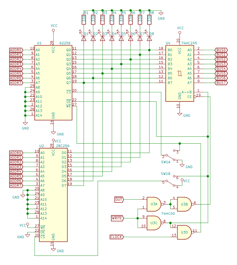
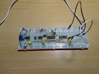
8 bit CPU: Soldering the boards
The boards arrived, so did parts. Time to put it all together.
I've chosen to make boards using SMD parts, soldering those might sound a little scary. What I remember from previous experience (I've soldered a couple of small boards before), it is easier than one could think before trying.
Tool-wise it also does not require anything fancy. Good tweezers, small soldering iron, flux pen. Solder wick could be useful, but I did not need that very often. It helps to have brightly lit workplace.
Soldering SOIC chip on the board so that it is connected properly is quick and easy. It takes a bit longer if one wants to align it perfectly. Solder one corner pin, check alignment, re-melt and correct until you're happy, then do one in the opposite corner. Finish with the remaining pins. 0805 resistors and capacitors also are quite easy - solder one pad, check, re-melt. Once happy - solder other one.
What I struggled a bit with was LEDs. Again - it is not hard to put them on board and solder (they also are 0805 size), it is hard to align them. When LEDs are placed in a row, it is very visible if they are even a tiny bit off. Later I invented a technique that helps get more precision - taped a thick paper on the board and used it as a guide.
My boards have components on both sides, soldering first one is fine, but becomes tricky when you flip the board over. Boards are designed to be plugged into breadboard, so I used headers as a support. Once I was done with SMD parts - soldered the headers last.
The most difficult thing to solder was the PLCC socket for my EEPROM writer. I managed to do it, but not without damaging the plastic part. Will have to do some research how to do it properly when time will come for Control Logic or Output Register boards.
Here's a real-life register board:
And when flipped over:


Comments
Post a Comment