8-bit CPU: Test module and Python-assembly code
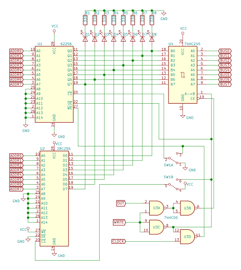
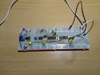
I have ALU block and Memory block, as a next step I wanted to connect both of them to my Arduino test device. It worked, but was very clumsy (3 devices, held together just by wires). I decided to re-build the Test module differently - on breadboard, so I can connect modules together.
It is an Arduino Nano, driving a pair of 74HC595 shift registers. To expand further, 3 pins from each shift register drives 74HC138 demultiplexers. Control lines from demultiplexers are for Out and Load lines (7 for each type), the rest are for general purpose (for example - ALU's Subtract).
I played around with more tests, implemented ld and st "instructions" (load a register from memory location and store register value in memory) in my Python-assembly.
Then I started to think: there are 2 registers, ALU, Flags, memory. I even have some sort of assembly language. What if I try to implement something more interesting, utilizing resources I have?
The "classic" program for BE-SAP-1 computers probably is the Fibonacci sequence, but it felt too simple for me. What about Sieve of Eratosthenes then?
I started with code in C language, simple algorithm that finds prime numbers up to 16:
#include <stdio.h>

int p, m;
int seg0[16];

void main()
{
    // we're never accessing 0-th and 1-st, but it is more convenient
    // to declare it this way.
    seg0[0] = seg0[1] = 0;

    // fill seg0 with non-zero values
    for (p = 2; p < 16; ++p)
        seg0[p] = p; // any non-zero

    // print primes and mark multiples
    for (p = 2; p < 16; ++p)
    {
        if (seg0[p] == 0) continue;

        printf("%d\n", p);

        for (m = p + p; m < 16; m += p)
        {
            seg0[m] = 0;
        }
    }
}
So, how does it translates to my Python-assembly? The code is quite long, so I'll translate only first loop for now (you can see full source code here):
    ldi (A, 2)

    # fill seg0 with non-zero values
    while True:
        # calculate target address of seg0[A] in B
        ldi (B, seg0)
        add (B, A)

        stabs (B, A) # store value of A into address pointed by B

        # next index in A
        ldi (B, 1)
        add (A, B)

        # are we done?
        ldi (B, 16)
        cmp (A, B)

        # emulate conditional jump back to start of the loop
        if bne(): continue
        break
Note that this is still a Python code, calling normal Python functions (named ldi, add, stabs) and passing arguments that are normal Python variables (named A, B, seg0). Yet it feels like an assembly language.
Each "instruction" is interpreted by code that sends appropriate control signals to real hardware. For example: ldi (A, 2), will enable A register's Load line, put a value 2 on the Bus and pulse a clock. As a result, value 2 will be loaded in the register.
In Python there are no labels and goto, making jumps impossible. It is, however, quite easy to emulate the behavior using loops, break and continue. The bne() function checks Flags register and returns True if jump back to the start of the loop has to be taken. I could have also written if not bne(): break there, but I think first variant should produce shorter machine code (when I eventually get to that).
The end result is a strange mix, where all program logic is in Python, but all program state is in the real hardware. Why I'm doing this? If I could translate the "instructions" into machine code, and the computer was complete, I think the program would run just fine. This way I can already start to write (and even debug) quite complex programs for it.


Comments
Post a Comment