8-bit CPU: Quarter-Clock
My Clock module worked fine (to be honest, I did not use it that much), but I have some new ideas to try out. Also, as I'm approaching the end of first stage of my build, the requirements for the Clock has changed. I could try to "patch" the existing module, but it's actually easier to re-build it on a new breadboard.
At first, however, I had to play around with Digital simulator, it might have been quite hard to iron out the details building hardware directly. Here's what I came up with:
Alternate debouncing
Switch debouncing, utilizing monostable mode of 555 timer (as in Ben's original design) has a nasty shortcoming - release of button is not properly debounced, meaning that one might get extra pulses when releasing it. I've seen several attempts by community members (and even Ben himself) to compensate, but none of the solutions felt appealing to me. So I decided to "attack" the problem from different angle.
Instead of using monostable mode, I decided to run an astable timer at ~100 Hz, driving clock input of a D flip-flop (74HC74). Input of the flip-flop is connected to a button.
It works by "scanning" the current state of the button every 10 ms and latching it. If the "scan" happens on the moment when button bounces, flip-flop will still load either 0 (state, button was 10 ms before) or 1 (state, it will be after 10 ms). Unless it is an extra "bouncy" switch, that takes longer than 10 ms to settle, we should get a clean transition. It also works for button release.
This is the left-bottom part of the circuit.
25% duty-cycle outputs
When I built Memory module, I did not add any edge-detection circuits there. Main goal of edge-detection is that value written to RAM is one that was on the rising edge of the clock. Ben solved it by using a RC-circuit to get a short pulse (10 μs, I believe). It worked for him fine, but appears to cause lots of issues for other builders. There's another edge-detection technique, utilizing logic gate propagation delays, giving a pulse on nanosecond scale.
I decided to move the feature to the Clock. It might seem a lot of effort for just a
single operation in different module - RAM write. However, it could be useful elsewhere.
For example, I plan to build a Stack Pointer register eventually. Most likely it will consist from 74HC193 up/down counters. Since those have asynchronous load, I'll
need an edge detector there as well.
Nothing, really limits the length of the write pulse, as long as everything (address lines and data) stays steady. What if we keep the write signal on for longer - a quarter of the clock cycle? Then disable it for another quarter before the inverted clock hits.
Why 25% duty cycle, instead of RC or propagation delay generated pulses? This way there's no need for separate "clock edge" line, carrying fast-changing pulses. I can use same clock signal everywhere. Unless frequency starts to approach limits of the logic gates, I do not see any downsides.
The rightmost part of the circuit has NAND gate, used as inverter, another D flip-flop, acting as a frequency divider. It's outputs, NOR-ed with the inverted input clock signal gives a nice 25% duty-cycle signals for primary and "inverted" output clocks.
Technically, there was no such requirement for inverted clock, but why not?
Manual pulse improvements
The quarter-pulse generator actually divides the input frequency in half. It's fine for "automatic" clock, as it can simply run twice as fast to compensate. The case with manual clock is different - one would have to press button twice for single full clock cycle. It might be a little inconvenient.
It can be avoided, however. We should send a "primary" clock pulse when button is pressed and "inverted" one when button is released. If we do not mess up the number of pulses, it can be reduced to generating a pulse on button press, and then another one when it is released. The quarter-pulse generator will do the rest.
To achieve that (as shown the bottom-left part of the circuit) we add another D flip-flop, that "scans" the output from the first debouncing flip-flop. When button is pressed (or released) it will load that value a single scan-clock cycle later. For the duration of that cycle, outputs of both flip-flops will be different. We can feed that into XOR gate and get a 10 ms pulse whenever button is pressed or released. That in turn will become either primary or "inverted" pulse.
Mixing the signals and mode switch
Mixing auto and manual pulses does not call for much comments, just it turned out that the most convenient way to do that is using just NAND gates (instead of ANDs and OR).
What is the reason why one would press the manual pulse button? To operate the clock module in manual mode, obviously. Instead of adding a slide-switch, we can use same button to also switch into the manual mode.
This should be done carefully, through. It should keep the phase of odd/even pulses. Otherwise we can end up in a situation when button presses and releases sends "inverted" and primary pulses the wrong way around.
I had to experiment with it a lot in simulator to find the correct configuration. The mode switch occurs when (yet another) D flip-flop loads an inverted value of a button on a falling edge of primary output clock (inverting the signal using spare NOR gate).
It works like this: button is pressed, the value is latched into first, then second D flip-flop. At this point there will be no transitions and both the inverted output of second latch and output of the XOR gate will stay low. The automatic clock still runs and produces the primary output clock pulse as usual. Then as it falls, the mode is switched by loading a new value into mode-selector's flip-flop.
The primary pulse was sent, user is still holding the button down. What should happen next? When button is released, it produces a pulse, that happens to be an "inverted" clock output. Exactly the expected behavior.
What about getting back into automatic clock mode? Assuming nobody is going to hold both buttons down, there are no special considerations. We just switch the mode by triggering flip-flop's asynchronous preset pin.
This describes the middle part of the circuit.
Building it
The circuit felt quite complicated, so I decided to plan it first as a Fritzing project.
 As I need 2 timers, to save space I decided to use a TLC556 chip instead of two 555s. Single 14-pin chip takes less space on the board than two 8-pin ones, and the whole thing barely fits anyway.
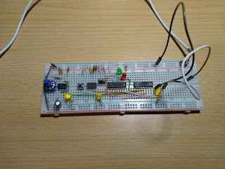
Once I was reasonably happy with the layout, built it on real breadboard.
I did not bother with LEDs in Fritzing, as they just block the view, but in real build they're a must-have 😉 The leftmost yellow ones show the auto and manual pulses, green and red is mode indication. Outputs are on the right, blue is primary, yellow - "inverted" signal.
Demo and conclusions
To make manual pulse signals more visible in video (they still barely shows) I've lowered the
"scan" clock frequency to 50 Hz. In real life I like the module better
when it's running at about 150 Hz.
I must admit, that I'm missing a feature - HALT signal. Could not find an easy way to add it without interfering with switching to manual mode. I suppose I'll have to add an extra output stage for it, but I do not feel that it is very important. Programs can restart or run an infinite loop after finished.
There's another feature I wanted to add - a BRK signal. CPU could use that to switch into manual mode - that might be handy for debugging. It'll also have to wait.


Comments
Post a Comment