Building a serial add-on board (part 1)
Writing code is not everything. No program is good until it can display it's results in some way. With regular programs it is easy - you just print something and it magically appears on screen or somewhere. Bare-metal programming is different. There is no underlying operating system to handle that "magic" and we have to make it happen on our own.
And it better be simple, remember, we are practically blind-folded at this point. Trying to send something over network or display on the screen is too complicated, it would never work, since there are too many things to go wrong. There's another simple interface - we could try to blink a LED on RasPi. And then send out our messages using say, Morse code. But that doesn't look too appealing either. Fortunately, RasPi have another simple interface, called UART. Using that we can send anything we want to computer's serial port (or emulated serial port, if computer has no physical ones).
But there's a catch. We can not simply wire up Raspberry Pi to a computer's serial port. The voltages on both ends are not compatible, an we would fry RasPi instead. So we need some sort of electronics hardware in between. And that's what I'm going to build.
There's a chip designed to do exactly what we need. MAX3232 transceiver translates 3.3V UART signal to serial port (RS-232) voltage levels and back. Basically what we need is to wire up a chip and additional components to RasPi's expansion header and computer's serial port.
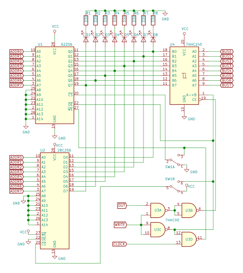
So, armed with MAX3232's data-sheet, RasPi expansion header's and RS-232 connector's pin-outs I fired up Cadsoft Eagle and came up with a very straight-forward schematic:
 I have to confess here, that I actually designed it for chip's cheaper cousin MAX232, hence 1uF capacitors instead of 0.1uF ones. Somehow I over-looked MAX232 characteristics and thought it will also work with 3.3V. It did not! But fortunately both chips are pin-compatible, and board built for MAX232 works great with MAX3232 in it. I'll return to it...
Next we need to lay out those components on a PCB. I intend to connect my board using ribbon cable, therefore I need not to worry about RasPi's dimensions and it's connectors. In the end I came up with design for small (40x45 mm) 1-sided board:

The complete Eagle project can be downloaded here. Use it as you like, as long as you do not blame me for anything.
Now everything is set and we need to produce the board somehow. Of course I could order some manufacturer to make boards for me. But manufacturers' pricing is not very flattering near me. And shipping costs from more distant places being more expensive than boards themselves do not like me either.
From the beginning, the reason, why I designed the board to be 1-sided and used fairly wide traces and clearing, was that I intended to make one at home. Real DIY style.
How? That's up to Part 2.
And it better be simple, remember, we are practically blind-folded at this point. Trying to send something over network or display on the screen is too complicated, it would never work, since there are too many things to go wrong. There's another simple interface - we could try to blink a LED on RasPi. And then send out our messages using say, Morse code. But that doesn't look too appealing either. Fortunately, RasPi have another simple interface, called UART. Using that we can send anything we want to computer's serial port (or emulated serial port, if computer has no physical ones).
But there's a catch. We can not simply wire up Raspberry Pi to a computer's serial port. The voltages on both ends are not compatible, an we would fry RasPi instead. So we need some sort of electronics hardware in between. And that's what I'm going to build.
There's a chip designed to do exactly what we need. MAX3232 transceiver translates 3.3V UART signal to serial port (RS-232) voltage levels and back. Basically what we need is to wire up a chip and additional components to RasPi's expansion header and computer's serial port.
So, armed with MAX3232's data-sheet, RasPi expansion header's and RS-232 connector's pin-outs I fired up Cadsoft Eagle and came up with a very straight-forward schematic:

Next we need to lay out those components on a PCB. I intend to connect my board using ribbon cable, therefore I need not to worry about RasPi's dimensions and it's connectors. In the end I came up with design for small (40x45 mm) 1-sided board:

The complete Eagle project can be downloaded here. Use it as you like, as long as you do not blame me for anything.
Now everything is set and we need to produce the board somehow. Of course I could order some manufacturer to make boards for me. But manufacturers' pricing is not very flattering near me. And shipping costs from more distant places being more expensive than boards themselves do not like me either.
From the beginning, the reason, why I designed the board to be 1-sided and used fairly wide traces and clearing, was that I intended to make one at home. Real DIY style.
How? That's up to Part 2.


Comments
Post a Comment