Building a serial add-on board (part 2)
In Part 1 we discussed why we need a serial add-on board and designed one. Now it's time to actually build one.
Of course we will require some tools, materials, and chemicals, I'll describe them along the way.
First and foremost, we need a material for PCB. I'll use 1-sided FR-4 epoxy laminate. I've been lucky to acquire an enormous piece (1/2 sqm. or so) in a garage sale. But it should be available at most DIY electronics stores. As I mentioned earlier, we will require a piece with size 40 x 45 mm.
Draw the borders and cut it off with a hacksaw.

Do not worry, if you can not quite follow the line and your cuts are not very straight. You will be able to trim it to right dimensions using a file. Smooth any sharp edges as well, while you're at it.

Note, that dust from sawing and filing FR-4 might be hazardous, so I'm doing this outside.
Now it's time to clean it. I'll use a kitchen sponge with a bit of laundry detergent on it.

Rub it until you get clean, shiny copper surface. Wipe it dry afterward.

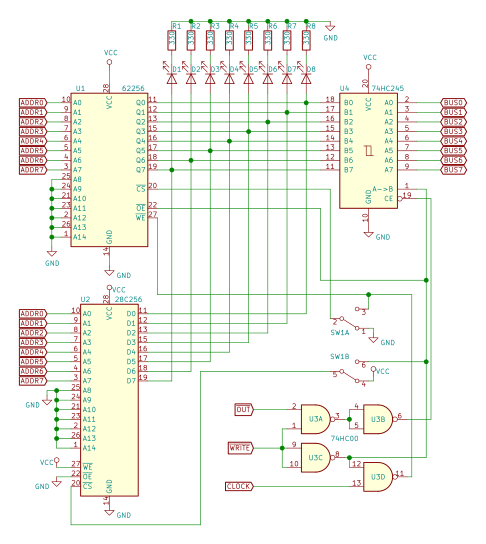
Next, we'll prepare our board image for transfer onto copper. Open Eagle, hide all unnecessary layers, leaving only Bottom, Pads, Vias and Dimension. You should see only what you are going to transfer to copper. Now print it on glossy paper using laser printer (inkjets or other printer types will not work). Use Black, Solid options in Eagles's print dialog. You should get something like this:

I used paper from marketing booklet for some software package. Check it, imagine that your board is transparent and you're looking at your PCB from component side. Now cut it out and place on piece of laminate, we prepared earlier, printed side facing copper.

Heat up an iron (regular, not soldering one) on wool to cotton setting. Place a piece of clean paper on top of the board and apply iron. Keep it still for a minute or so, and then keep "ironing" for another 10.

Remove the iron and let the board to cool off. Then place it in warm soapy water for a half of hour or so.

Paper now will be soaked and should come off easily, leaving our printed image on copper. Be sure to remove all the paper, do not forget the drilling holes. Use wooden toothpick where necessary. You should get something like this:

Now, the image is transferred onto copper and looks good. If you do not like what you see, use paper towel and acetone to clean it off and start over. To continue we will require a chemical called etchant, to remove excess copper. I'll use Ferric chloride, but there are different etchants available. FeCl3 is pretty nasty chemical, be careful.

Now we wait. In an hour or so, etchant will remove exposed copper, leaving only what's protected by toner. Here, I'm almost done:

Only few more minutes to go. Note that solution turned from orange to greenish-brown, now it's mostly CuCl2.
Once all the excess copper is gone, rinse the board thoroughly under running water. Then use paper towel and acetone to clean the toner off. Here we go:
 Closeup...

Here we have our board, built at home using simple tools. In Part 3 we'll finish our board, see what else can go wrong and finally power it up.
Of course we will require some tools, materials, and chemicals, I'll describe them along the way.
First and foremost, we need a material for PCB. I'll use 1-sided FR-4 epoxy laminate. I've been lucky to acquire an enormous piece (1/2 sqm. or so) in a garage sale. But it should be available at most DIY electronics stores. As I mentioned earlier, we will require a piece with size 40 x 45 mm.
Draw the borders and cut it off with a hacksaw.

Do not worry, if you can not quite follow the line and your cuts are not very straight. You will be able to trim it to right dimensions using a file. Smooth any sharp edges as well, while you're at it.

Note, that dust from sawing and filing FR-4 might be hazardous, so I'm doing this outside.
Now it's time to clean it. I'll use a kitchen sponge with a bit of laundry detergent on it.

Rub it until you get clean, shiny copper surface. Wipe it dry afterward.

Next, we'll prepare our board image for transfer onto copper. Open Eagle, hide all unnecessary layers, leaving only Bottom, Pads, Vias and Dimension. You should see only what you are going to transfer to copper. Now print it on glossy paper using laser printer (inkjets or other printer types will not work). Use Black, Solid options in Eagles's print dialog. You should get something like this:

I used paper from marketing booklet for some software package. Check it, imagine that your board is transparent and you're looking at your PCB from component side. Now cut it out and place on piece of laminate, we prepared earlier, printed side facing copper.

Heat up an iron (regular, not soldering one) on wool to cotton setting. Place a piece of clean paper on top of the board and apply iron. Keep it still for a minute or so, and then keep "ironing" for another 10.

Remove the iron and let the board to cool off. Then place it in warm soapy water for a half of hour or so.

Paper now will be soaked and should come off easily, leaving our printed image on copper. Be sure to remove all the paper, do not forget the drilling holes. Use wooden toothpick where necessary. You should get something like this:
Now, the image is transferred onto copper and looks good. If you do not like what you see, use paper towel and acetone to clean it off and start over. To continue we will require a chemical called etchant, to remove excess copper. I'll use Ferric chloride, but there are different etchants available. FeCl3 is pretty nasty chemical, be careful.

Now we wait. In an hour or so, etchant will remove exposed copper, leaving only what's protected by toner. Here, I'm almost done:
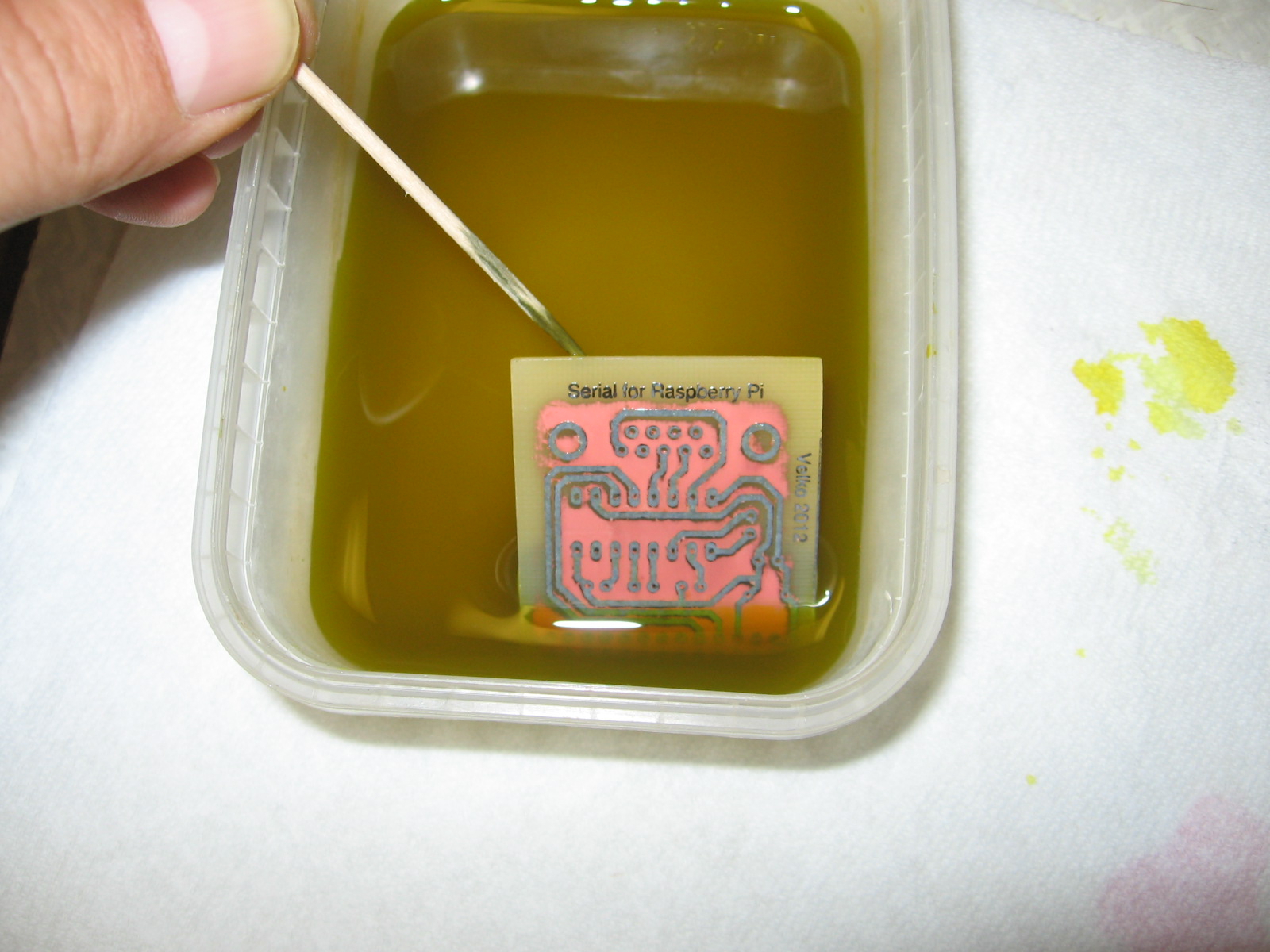
Only few more minutes to go. Note that solution turned from orange to greenish-brown, now it's mostly CuCl2.
Once all the excess copper is gone, rinse the board thoroughly under running water. Then use paper towel and acetone to clean the toner off. Here we go:


Here we have our board, built at home using simple tools. In Part 3 we'll finish our board, see what else can go wrong and finally power it up.


Comments
Post a Comment