8-bit CPU: Display (part 1)
In his series, after building the clock module, Ben started to work on registers. Those are important parts of the computer, but feels a little underwhelming again. So I decided to go for output display instead.
The module requires a clock for multiplexing its output to four 7-segment displays. The clock should eventually be independent from the main clock and run much faster. But in the meantime other parts of the computer do not exist yet, and I might like to run it really slow. So I just placed the 555 on the board, but did not even bothered to wire it up. I'll just use signal from my freshly finished clock module. I haven't really used it for anything yet!
Ben used 74LS76 JK flip-flop to manually build a 2 bit counter. I just went for 74HC163. It's a 4-bit counter, but there's no harm in using only two outputs. Wired counter to inputs of (one side of) 74HC139 2-to-4 demultiplexer - that should allow us to cycle the displays.
I was anxious to see if I'm on the right path so I added LEDs to the output of the demux, connected clock module and powered it up. I was not a surprise that it worked as expected, but still was an exciting moment. It's my first build using logic chips, that does something more complicated than blinking a LED.
With that sorted out, I could proceed and move the 7-segment displays from my Arduino prototyping board to the right side of this breadboard. Luckily I had not to prepare the connecting wires again, the layout stays the same, I'm just moving them to another board.
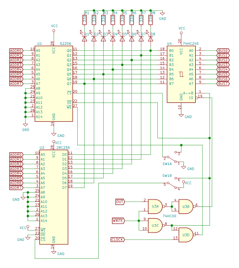
Next I placed an AT28C64 EEPROM on the board and tried to figure out how to fit in current limiting resistors. Damn, that 28-pin EEPROM is huge. I could not locate 28C16, so I went with a bigger one (still smallest I could get).
The good practices call that for LEDs connected in parallel, there should be a current limiting resistor for each LED. This is also case with 7-segment displays. The technique ensures that each segment gets same current (and has the same brightness) regardless if other segments are lit or not.
So in this setup (with common-cathode displays) it calls for a resistor on each positive side of the display - on the 8 wires coming from EEPROM. That was the configuration I connected them in my previous Arduino build.
If I placed my chips end-to-end, without any gaps between them, I could probably squeeze them in. But otherwise I managed to find a place for just 4 of them. Well, it looks like I'll have to deviate from the good practices. There are 4 wires coming from displays and going into 74HC139 demultiplexer. It's not ideal, as now segments when showing digit '8' will be less bright compared to when displaying '1'. But well, it's a prototype, it'll have to do. I'll just keep that in mind for PCB version.
In one of my next builds I found out the hard way, that trying to squeeze in parts tightly on breadboard is not such a good idea.
While wiring up EEPROM, I decided to deviate (again) a bit from Ben's design. He used A8 and A9 address lines for selecting the display (ones-place, tens-place, etc.). I decided that I'll use A0 and A1 for that.
It won't change how the device works in the end, but will make a lot neater data layout in the EEPROM. In my case, each mapping for number will consist from 4 subsequent bytes. In Ben's case - they are scattered all over the place.
On the other hand - address lines A0 to A7 are conveniently placed next to each other on one side of the chip, but A8 and A9 are placed on the other. This adds a little annoyance when wiring up the input lines. Well, no design is perfect!
Hardware-wise I'm almost done. The 555 is not connected yet, but I'll just use the clock module for the time being. There's a bigger problem though - the EEPROM is blank now and no matter how I connect the address lines, It just shows "8.8.8.8."
I can, however, remove the EEPROM and connect some jumper wires to get funny symbols on the displays.

If you look very carefully, the picture does not match the story exactly. I forgot to snap a picture at that time.
I'm using those 2 incoming address lines to get different symbol on each display, proving the basic principle. But to display normal digits, I have to program the EEPROM. For that I have to build an EEPROM burner first.


Comments
Post a Comment