8-bit CPU: Display (part 2)
Earlier I worked on a display module, but could not proceed because I had no means of programming an EEPROM. I had to step aside for a moment and build a device that can do that.
Now I have programmer, but what data should I write on the chip? Well, Ben explained the main idea quite carefully in a series of videos, but my build differs a little.
One thing is - I did not follow the videos exactly, so I'm fairly certain that I have connected display segments to EEPROM's data output pins differently. In Ben's video there were several wires, connecting pins on different sides of EEPROM and displays. I have just one.
Ben mapped every digit on a paper and carefully worked out the byte values for each. I suppose it's fine if you want to show the process in detail. But I have lazier idea - let C compiler and Arduino do it for me. They are much better at performing tedious calculations. I'll just set the rules.
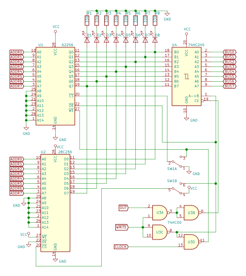
For starters, I have to figure out which bit is connected to which segment. I could probably trace the wire from EEPROM to the display, then look up in datasheet which pin controls which segment. But there's an easier way - just try it out. Remove the EEPROM, grab a jumper wire and connect data lines to +5V one by one. See what lights up and write it down as #define in code.

Got something like this (showing just 2 lines of 8):
#define SEG_BIT_A       (1 << 5)
#define SEG_BIT_B       (1 << 4)
The (1<<4) translates to 0b00010000, but expresses the intent more clearly: we want a value with only bit #4 set. Here segment B appears to be connected to EEPROM's data pin IO4.
Now, when we have all segments mapped out, we can combine them to get digits. For example: digit '4' should have segments B, C, F and G lit. If we translate that to code we get:
#define DIGIT_4 (SEG_BIT_B | SEG_BIT_C | SEG_BIT_F | SEG_BIT_G)
I am not sure what byte value exactly that produces, but actually it doesn't matter. If rules are set correctly it will just work. If not - I've probably misspelled something (or the whole idea is wrong 😉). If I decide to rewire the display differently, I'll just have to update few #defines. The point is - I'll never have to re-calculate the whole table by hand.
I decided to re-arrange the data on EEPROM, so that mappings for
numbers are together. I'll have 4 bytes for value 0, next four - for 1
and so on.
Because of that I can process one value, write the bytes to EEPROM and move on to the next. I do not have to return multiple times for the value, to get ones-place, tens-place and so on. There are no calculations involving division and taking reminder needed, I can just use sprintf() function to format the value as text (I suspect, sprintf() does something similar internally anyway, but I do not have to worry about it) and then map each character (not to be confused with value it represents) to the digit. One small thing - since I like little endian better, I chose to store patterns for displays (ones-place, tens-place) from right to left. So I have to process the formatted text backwards, but that is not a big problem.
My EEPROM has 4 times more capacity compared to ones Ben used, so I do not have to choose carefully what extra display mode to add. I filled it with mappings for decimal unsigned, decimal signed, hexadecimal and octal display modes. And I still have space for 4 more.
EEPROM is programed now, let's put it in, arrange wires lines for some random input, power it up, and crank up the speed of the clock.

Ok, it shows something, and if I change the input it shows different value. Now, how do I know it works correctly? One thing that comes in mind is to connect it to Arduino, write a program that counts and outputs all possible byte values. Additionally: connect those 2 mode-select wires and cycle the display modes. Then I'll just have to observe it running for few minutes. One more finishing touch: let's connect that 555 chip.

Observations did not reveal any anomalies, so I can consider this done for now and move to other things. Notice that I did not add any register chips to it. That's because I intended to build just a display device, not an output register. I'm sure I will merge those eventually, but for now I plan to use the display independently.
After I have used the display for some time now, I've noticed few shortcomings. But nothing major, I'll try to fix them later.


Comments
Post a Comment