Posts

8-bit CPU: Going virtual

Image
A lot of time has passed since my last post about the 8-bit CPU, life happened and I did not have that much time to work on the hardware anymore. The itch was still there and I could occasionally work on it. Not enough to advance the hardware build much, but I could do software side from time to time. Recap I " went live " with the CPU and swapped out my Test module for EEPROM-based Control Logic. Now the CPU works stand-alone, but I still have the Arduino sketch and lots of Python code to command it. My long-term plan is to re-connect it and use for system diagnostics and program debugging, but for now I'll set it aside and go with a software implementation. What exactly that Test module was and how did it work? It was an Arduino + few '595 shift registers and '138 demultiplexers. These were connected to control signals of the CPU modules. For example, if I wanted to output the contents of the A register onto the bus, I'd load the corresponding combination o...

Packaging CustomAsm for Ubuntu

Image
I'm using CustomAsm to compile code for my  8-bit-CPU . It works quite nice locally, but I thought it would be nice, if I could also run the compilation as part of GitHub Actions workflow. I will not go into deep details about how to set up those workflows, there's documentation for that. Basically you create a .yml file in your Git repository for GitHub to act on. There's a choice of OSes for the workflows to run on, my selection is Ubuntu. There's a slight issue, though. CustomAsm is a Rust program and normally it is installed using cargo install command. To do that, each time I'd have to install Rust, compile CustomAsm and only then I'd be able to use it. It might work, but there's too much of preparation. Wouldn't it be nice, if I could just apt-get install customasm and be ready to use it. That's what I'm about to enable. Ubuntu Personal Package Archives In order for package to be installable in the runner , it must be available at pub...

8-bit CPU: Playing with FETs and new Display module

Image
My previous improvements on Display module left me a bit disappointed. The brightness of display just was not good enough. I could not push enough current into the LEDs. I purchased a batch of more efficient 7-segment displays, but I still want to make the old ones work.

8-bit CPU: It's alive!

Image
With updated version of Clock module complete, the only thing missing is the Control Logic. Let's build it to complete the CPU. Control logic The main idea of the Control logic is the same as in Ben Eater's CPU, with the difference that I'm using 28C64 EEPROMs. The address line usage is a bit different, through: 3 lines from microstep counter, allowing 8 microsteps in total 4 flags from Flags register 6 lines from Instruction Register, allowing 64 instruction opcodes This uses all 13 address lines, whole 8 KiB of the EEPROM, no room for byte-select bit, the contents of each ROM will have to be different. Notice, that I moved Flags bits to the middle of the input address. I like this layout better, because now all bytes for an instruction are grouped together. It also allows for easy expansion to 256 opcodes, the data layout will stay the same, I'll only need to replace EEPROMs with larger ones (28C256) and connect remaini...

8-bit CPU: Quarter-Clock

Image
My Clock module worked fine (to be honest, I did not use it that much), but I have some new ideas to try out. Also, as I'm approaching the end of first stage of my build, the requirements for the Clock has changed. I could try to "patch" the existing module, but it's actually easier to re-build it on a new breadboard.   At first, however, I had to play around with Digital simulator, it might have been quite hard to iron out the details building hardware directly. Here's what I came up with: There's a lot is going on, I'll try to explain step by step.

8-bit CPU: Generating machine code

I developed some demo programs using an assembly-like constructs in Python. All is nice and it utilizes real hardware for calculations. Still that is just Python code running on PC and sending control signals to my registers, ALU and memory. Eventually, I'll have to run the code on the 8-bit computer autonomously. For that I need to convert it to sequence of binary instruction opcodes and arguments - machine code. I've also tried to hand-assemble some simple programs, but it feels quite tedious and error-prone.

8-bit CPU: Putting it together

Image
Looking at modules I have built so far, I realized that I have almost all I need for a complete computer. Long time ago I built Clock module and Program Counter . I've just updated Output module , There's ALU, 2 general-purpose registers, Flags register . Also I have RAM module and MAR register . I even have an Instruction Register. What's missing? Control Logic, of course!

8-bit CPU: Display updates

Image
The display module turned out quite nice, but there were some flaws I wanted to fix. In order to connect the module to the Computer, some additional hardware has to be added as well. Flicker I noticed that with a corner of an eye I can catch some flickering, but when I at it directly, it appears to be fine. Ben used 10 nF capacitor and 100 K resistor with 555 timer. I had no 100 K resistor, so I used 330 K instead. If we put the values in NE555 calculator , it gives around 218 Hz. Each display switches 4 times slower, resulting in 54 Hz. My eyes have always been sensitive to flicker, I remember when old CRT monitors gave me headaches with their 60 Hz. After short consideration I replaced it with 10 K resistor. It pushes up the frequency to almost 7 kHz. While this may feel as an overkill, all chips are rated for much higher frequencies than that. And now there definitely is no visible flickering. Mode indication I found out that it is a bit confusing not to know in which mode ...

8-bit CPU: Test module and Python-assembly code

Image
I have ALU block and Memory block, as a next step I wanted to connect both of them to my Arduino test device. It worked, but was very clumsy (3 devices, held together just by wires). I decided to re-build the Test module differently - on breadboard, so I can connect modules together. It is an Arduino Nano , driving a pair of 74HC595 shift registers. To expand further, 3 pins from each shift register drives 74HC138 demultiplexers. Control lines from demultiplexers are for Out and Load lines (7 for each type), the rest are for general purpose (for example - ALU's Subtract). I played around with more tests, implemented ld and st "instructions" (load a register from memory location and store register value in memory) in my Python-assembly. Then I started to think: there are 2 registers, ALU, Flags, memory. I even have some sort of assembly language. What if I try to implement something more interesting, utilizing resources I have?  The "classic" program for BE-SAP...

8-bit CPU: Memory

Image
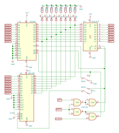
Time for another important part of the computer - memory. Here I think I have to come up with my own design. Ben's version has only 16 bytes, uses nowadays-exotic 74189 memory chips and there are DIP switches for programming. For the memory I plan to use 62256 SRAM chip. It can store 32 KiB of data, I initially plan to use just 256 bytes, so I'll connect remaining address pins to GND. I'm also not in a mood for any DIP switch based programming, so I'll add an EEPROM instead. There are several ways how computer can utilize such setup: split the address space into program and data memory. This is how Ben's 6502 breadboard computer works. Some additional logic gates are used for chip selection, the main issue however is that it is not very flexible. use Harvard architecture , where program and data memories are completely separate. Reading and fetching instruction are two different operations: former accesses RAM, latter - ROM. This is how AVR microcontrollers (heart ...

8-bit CPU: Wiring and testing the new ALU

Image
Once I had soldered the boards I was eager to test them. At first I "poked around" using jumper wires and boards appeared fine. To be absolutely sure, however, I have to wire them together into a new ALU block and hook it up to my Arduino testing device. Boards are a bit elevated above the breadboards, so it seemed to be a good idea to run wires underneath the PCBs. To save on wiring, I opted for simple, fixed configuration (same as breadboard prototype and Ben's original), instead of my new, dual-output feature. I tested the dual-output some time later, adding jumper wires for missing connections. The concept works fine, but it takes 14 control wires to tame the beast. This will have to wait for proper control logic. The ALU block is not the only piece that is new. My new EEPROM writer features additional pin sockets, giving access to onboard shift register outputs. When no EEPROM needs to be programmed, it can be repurposed to switch control lines. I do not need my ad-h...

8 bit CPU: Soldering the boards

Image
The boards arrived, so did parts. Time to put it all together. I've chosen to make boards using SMD parts, soldering those might sound a little scary. What I remember from previous experience (I've soldered a couple of small boards before), it is easier than one could think before trying. Tool-wise it also does not require anything fancy. Good tweezers, small soldering iron, flux pen. Solder wick could be useful, but I did not need that very often. It helps to have brightly lit workplace. Soldering SOIC chip on the board so that it is connected properly is quick and easy. It takes a bit longer if one wants to align it perfectly . Solder one corner pin, check alignment, re-melt and correct until you're happy, then do one in the opposite corner. Finish with the remaining pins. 0805 resistors and capacitors also are quite easy - solder one pad, check, re-melt. Once happy - solder other one. What I struggled a bit with was LEDs. Again - it is not hard to put them on board and s...

8-bit CPU: design the PCBs

Image
The idea is clear, now the hard part: design the boards. I've been long time CatSoft Eagle user, but since they've been acquired by Autodesk, things have gone downhill. It did not even wanted to start on my machine (I use Linux as my primary OS). Well, so long and thanks for all the fish! KiCAD seems to be popular in the community , let's learn something new. As planned before, I started with ALU module. The schematics part was quite easy, there are no space constraints when drawing that. PCBs on the other hand... After board outline was set and connectors placed, it started to feel quite terrifying. Can I really fit ALL THAT on this small board? Eventually I did... Next I have to route the tracks, a lot of them. Felt a little lazy to do it all by hand and wanted to see what autorouter produces. Turns out, there is no such feature in KiCAD. Everybody appears to to hate autorouters! There was an option to export the board, autoroute it in FreeRouting and then import it ba...

8-bit CPU: Planning PCBs - architectural upgrades and addressing common issues

Image
I built a prototype ALU block and it appears to work fine, where to go now? I should remind that I do not want to build multiple copies of the same circuit. I already wired up the Program Counter board temporarily as B register. I'll need that for the intended purpose later. The logical step is to design a PCBs for parts I've built. I decided to start with ALU, Register and Flags boards. I had some extra ideas for features and improvements, that are not tested on breadboards. The changes are not that complicated so I decided to implement them directly to PCBs. Some of them will allow greater flexibility later on, some should help to prevent come common issues other builders are facing. As for PC, I decided to keep it on breadboard, as only one copy is needed and I'm not really decided if I want to do something different there. Flags I decided to deviate from Ben's design and build Flags register as a separate entity. The main reason is that at some point I plan to build...

8-bit CPU: ALU and Flags

Image
Now that I have a pair of devices that can store a byte, I can proceed to do something more interesting. Build a device that add them together, for example. In other words - let's build an ALU. The design follows same basic idea as Ben's - two 4-bit adders, XOR gates and an output buffer. I'm using HC logic here, so I used 74HC283, 74HC86 and 74HC245 chips. Since I've built only one Register and did not want to build another, I connected my Program Counter board as register B. If I keep the counting function disabled, it serves the purpose just fine. It took a lot of wires, but I'm just getting started, let's build Flags register as well.  There were no surprises with Zero flag - 4 NOR and 3 AND gates does the job - just following the Ben's design. Another latch (74HC173) chip to store it, done. The fun starts with the Carry flag: I wanted to support a carry-in signal for the ALU. It is very useful if one wants to perform the addition or subtraction for wid...

8-bit CPU: Register and counter

Image
I decided to proceed with the "boring" parts - Register A  and Program Counter. Building a register was completely uneventful. The only difference from Ben's build was that I used 74HC** series of logic chips, and in order to add current limiting resistors for LEDs, had to move them to the right (and add additional 8 wires).

8-bit CPU: Display (part 2)

Image
Earlier I worked on a display module, but could not proceed because I had no means of programming an EEPROM. I had to step aside for a moment and build a device that can do that. Now I have programmer, but what data should I write on the chip? Well, Ben explained the main idea quite carefully in a series of videos, but my build differs a little. One thing is - I did not follow the videos exactly, so I'm fairly certain that I have connected display segments to EEPROM's data output pins differently. In Ben's video there were several wires, connecting pins on different sides of EEPROM and displays. I have just one. Ben mapped every digit on a paper and carefully worked out the byte values for each. I suppose it's fine if you want to show the process in detail. But I have lazier idea - let C compiler and Arduino do it for me. They are much better at performing tedious calculations. I'll just set the rules. For starters, I have to figure out which bit is connected to w...

8-bit CPU: EEPROM burner

Image
In previous post I got to the point where I need to program an EEPROM, but have no device to do that. This time I'll try to build it. Ben had similar side-build as part of his Output register , so this should be a replica of that, right? Well it could have been, but I did not follow his footsteps exactly. First, I do not have Arduino Micro , just an Uno with a half-size breadboard attached to it. So I was planning to use that. I could not source 74HC595 shift registers, so I got 74HC594 instead. As it turned out later, they are so similar, that there actually are no differences for this use-case, but I did not compare them carefully at the beginning. Also, I was not following the video exactly, just got the main idea about shift registers and continued on my own. Placed the chips on the small breadboard, but there was a problem - the breadboard was a little too short. I placed chips end-to-end without any gaps in between, and there was just enough holes to fit all the pins. Unfort...

8-bit CPU: Display (part 1)

Image
In his series , after building the clock module, Ben started to work on registers . Those are important parts of the computer, but feels a little underwhelming again. So I decided to go for output display instead. The module requires a clock for multiplexing its output to four 7-segment displays. The clock should eventually be independent from the main clock and run much faster. But in the meantime other parts of the computer do not exist yet, and I might like to run it really slow. So I just placed the 555 on the board, but did not even bothered to wire it up. I'll just use signal from my freshly finished clock module . I haven't really used it for anything yet! Ben used 74LS76 JK flip-flop to manually build a 2 bit counter. I just went for 74HC163. It's a 4-bit counter, but there's no harm in using only two outputs. Wired counter to inputs of (one side of) 74HC139 2-to-4 demultiplexer - that should allow us to cycle the displays. I was anxious to see if I'm on the...

8-bit CPU: Clock module

Image
The parts are finally here an I can have some fun! Since nothing runs without clock, I decided to start with that module. It's probably not the most fun one, but I definitely need it, before doing something else. I was planning to follow Ben's design to some point. I had some TS555CN timers at home, so I decided to try those first, before opening the package with the new ones I ordered. Wired up the 555 in basic astable configuration with capacitors, potentiometer and decided to test if it works. So I connected a LED to the output and powered it up. It worked. Well, sort of. LED blinked and I  could adjust the frequency, but then suddenly it started to blink very fast, then again back to normal. What's even stranger I could trigger or suppress the effect by touching either chip or capacitor (just top of the chip, not the leads). I did accidentally connect my power backwards on first try 😓, so I figured it caused some damage or something. Replaced the chip with one of my n...